This manual covers a range of appliances. The following combinations are the First/First & Second Digits of the Model No’s covered.
 | MT - Double Door - eg MTA332V |
| MB - Combined - eg MBA3841C |
| T - Double Door - eg TA3PXUK |
| B - Combined - eg BE13PSUK |
This manual covers a range of appliances. The following combinations are the First/First & Second Digits of the Model No’s covered.
| MT - Double Door - eg MTA332V |
| MB - Combined - eg MBA3841C |
| T - Double Door - eg TA3PXUK |
| B - Combined - eg BE13PSUK |
| No Frost with LCD Display | No Frost with Standard Controls | |||||||||||||||||||||||||
| Controls |  |
 |
||||||||||||||||||||||||
| Sensors |
|
|
||||||||||||||||||||||||
| Inter PCB Connection | Ribbon cable that passes through fridge door and fridge door hinge area | Not Applicable | ||||||||||||||||||||||||
| Main Components |
|
|
The following conditions will prevent the Compressor from running even though compartment temperatures have dropped below set temperatures.
| Compressor Protection - This prevents the compressor from switching on for 8 minutes from the time that it last switched off. |
| After 4 hours of continuous running - The compressor will automatically cease running if this situation has occurred. |
| Pause After Defrost Cycle - After every defrost cycle there is a 10 minute pause period before the compressor starts to run. This ensures that the water from the defrost has time to run off before cooling down starts. |
| Electronic PCB Management |
| Compressor Control Circuit on PCB |
| Wiring Connections/Harnesses |
| Faulty Compressor |
| Temperature sensors Open/Short Circuited |
The start and end of the defrost cycles are controlled by the Electronic PCB, which will take the following circumstances into account.
Start of Defrost:
| The total run time of the compressor since the last defrost cycle (on average 11 hours). However the run time between two defrost cycles will be 30 hours maximum and 8 hours minimum. |
| The duration of last defrost cycle |
| The amount of door openings |
End of Defrost:
The cycle will end when the temperature of the evaporator reaches approx. 15°C, which in most cases is approx. 40 mins after the cycle has begun.
| Electronic PCB Management |
| Defrost Heating Elements Control Circuit on PCB |
| Wiring Connections/Harnesses |
| Thermal Fuses |
| Heating Elements |
| Blocked Drain Hole |
The following situations will prevent the Fridge fan from operating.
| If the fridge door is open even if the compressor is running |
| After the door is closed the fan will operate for a period of 3 secs to prevent any warm air that has entered the compartment from travelling down to the freezer compartment |
| After a defrost cycle and when the compressor starts running the fan will not run until the evaporator coil reaches -17°C. This is on top of the normal 5 minute delay. |
| Electronic PCB Management |
| Fridge Fan Control Circuit on PCB |
| Wiring Connections/Harnesses |
| Fridge Fan |
The following situations will prevent the Fridge fan from operating.
| If the fridge door is open even if the compressor is running. |
| After a defrost cycle and when the compressor starts running the fan will not run until the evaporator coil reaches -17°C. This is on top of the normal 5 minute delay. |
| Electronic PCB Management |
| Freezer Fan Control Circuit on PCB |
| Wiring Connections/Harnesses |
| Freezer Fan |
| If the fridge door is left open for a period of greater than 2 mins the lamps will start to operate intermittently, switching on & off at regular intervals. |
| If the fridge door is left open for a period of greater than 7 mins then the frequency of flashing will increase. |
| Electronic PCB Management |
| Fridge Door Control Circuit on PCB |
| Lamp Control Circuit on PCB |
| Wiring Connections/Harnesses |
| Fridge Lamps |
| Presence of magnet on the fridge door |
| If the temperature of the evaporator reaches 72°C the thermal fuses will operate. This cut off all power to all heating elements. |
| Thermal Fuses cannot be reset and therefore have to be replaced before the appliance will start to operate as normal |
| Wiring Connections/Harnesses |
| Thermal Fuses |
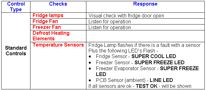
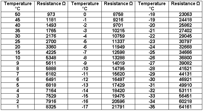
| All temperature sensors operate by using resistance values to control the required temperatures in each compartment. The Electronic PCB measures the resisitance values of the sensors. |
| If any of temperature sensors malfunction the appliance will still operate and no fault will be indicated to the user. The Electronic PCB uses a timed thermostat run to continue running the appliance this also includes a defrost cycle which again is a timed operation. |
| Electronic PCB Management |
| Temperature Monitoring Circuit on PCB |
| Temperature Sensors |
| Wiring Connections/Harnesses |
| Switch Appliance Off using On/Off Key |
| Press & Hold the ECO key for more than 3 secs |
| 255’s after activation |
| Switching the appliance Off by pressing the On/Off key |
| Disconnecting power |
| Switch Appliance Off by rotating Freezer knob to the Off position |
| Press & Hold the Super Freeze key for more than 3 secs |
| 255’s after activation |
| Switching the appliance Off by rotating Freezer knob to the Off position |
| Disconnecting power |