
HOTPOINT, INDESIT MOTORS
HERE`S WHAT I DO
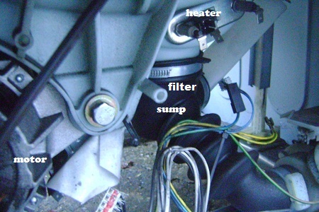 UNPLUG FROM MAINS.
Remove the rear access panel and the motor will be fixed to the bottom of the drum,wiggle and pull each of the wires to check they are secure.If the module is located at the bottom left of the machine , looking from the rear , then its got Indesit controls so it will have an indesit motor.
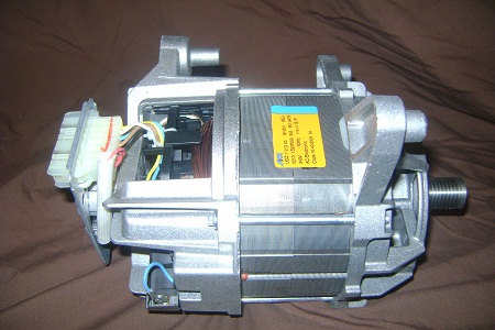 Remove the belt,unplug the wires and unscrew the two bolts,then push the motor it should slot back ( it may need a bit of a tap ) and can now be removed from the machine.This motor is off a wma machine , the later ones have the wires coming out the other end ,near the belt.
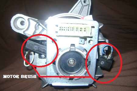 The majority of problems are down to worn brushes.The brushes are located on the rear of the motor , remove the two screws the brushes can be removed and inspected.There are lots of different types so i took the old ones into the shop and got the right ones.
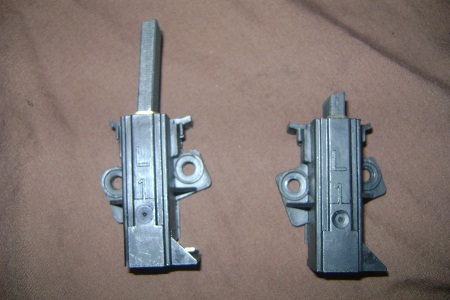 The new brush is on the left and the worn brush is on the right.A worn brush can cause drum not to turn,or the machine will lock the door and do nothing, or will pump for a second then stop then pump again .I always check the brushes .
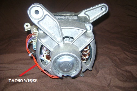 This is an 3 phase motor.Look no brushes.Can`t do much with these.The wiring connections are listed below .
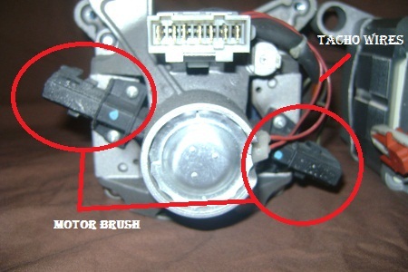 This is another type of motor.The two red wires shown in the picture are the tacho wires,when the motor turns it sends a signal down these wires and back to the pcb.
If these break then the motor will either go straight into a spin or the motor will try to turn quicker than normal then stop then try again.Because the pcb thinks the motor isn`t turning and sends more power ,to get it turning.
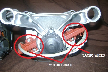 Another type of motor.
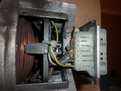
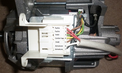 This is the Indesit motor( there are a few types of motor so i look for the tacho wires , and the armature wires go to the brushes you can determine which type it is and its not what it says on the machine).Taking 1 and 2 as the tacho wires , it`s easy to , determine the rest.The pins are numbered 1 to 7.The reading, when measured with a multimeter,is also listed.
Pins 1 - 2 Tacho wires.
Pins 3 - 5 Full field.
Pins 6 - 7 Armature.
Pin 4 Is the tapped field.
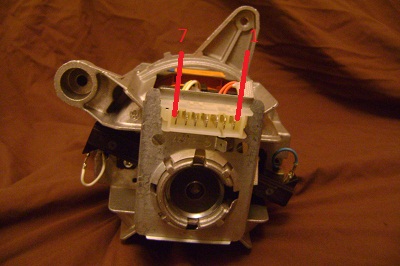 This is the Hotpoint fhp motor (there are a few types of motor so i look for the tacho wires and the armature wires go to the brushes,you can determine which type it is and its not what it says on the machine). Counting from right to left the pins are numbered 1 to 7.The reading, when measured with a multimeter,is also listed.
Pin 1 - 2 Tacho.
Pins 3 - 4 Field
Pins 5 - 6 Armature.
Pins 7 Field tap.
A circuit should be present through the windings and the field tap connects to the field windings to give the fast spins , if the tacho has failed the motor should turn fast then stop,as the pcb doesn`t know the motor is turning, and repeat or an error code .
| TESTING | FHP | CESET | BOSCH |
| TACHO | 135 ohms | 68.7 ohms | 200 ohms |
| CENTER TAP FIELD | 0.47 ohms | 0.41 ohms | 0.65 ohms |
| MAIN FIELD | 1.26 ohms | 1.25 ohms | 1.3 ohms |
| ARMATURE | 1.5 ohms | 1.78 ohms | 2.0 ohms |
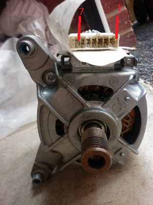 This is the 3 phase motor .Counting from right to left the pins are numbered 1 to 8 pin 8 isn`t used . The readings, when measured with a multimeter,are listed in the table below.
| TESTING | READING |
| MOTOR PROTECTOR 1 - 2 | 0.0 ohms |
| WINDING 3 - 4 | 6.4 ohms |
| WINDING 3 - 5 | 6.4 ohms |
| WINDING 5 - 4 | 6.4 ohms |
| TACHO 6 - 7 | 120 ohms |
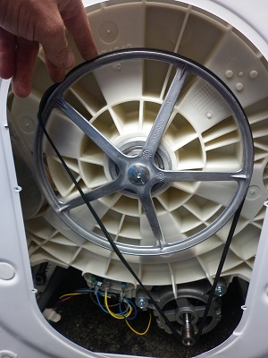 To fit the belt , place the belt around the motor and on the pulley until the belt goes tight.
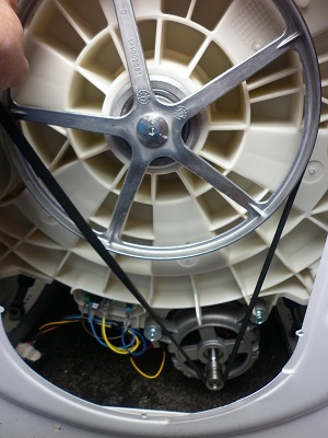 Then turn the pulley while holding the belt untill the belt stretches and slots into place.Make sure when the drum is turned , a couple of times , that the belt lines up central on the pulley .
